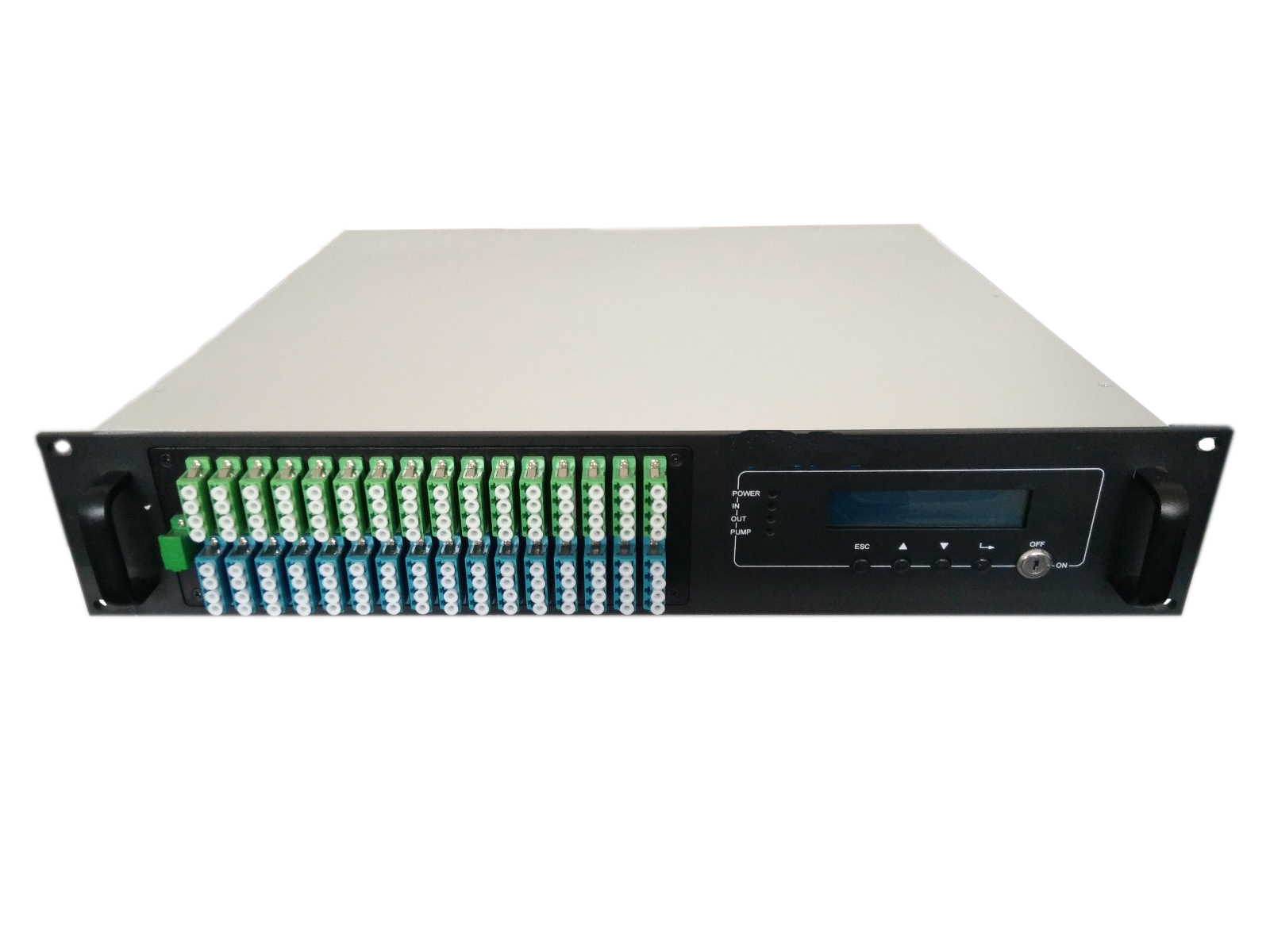
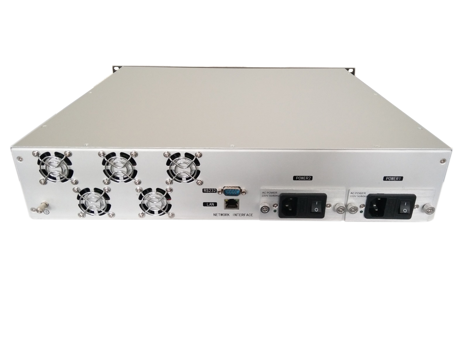
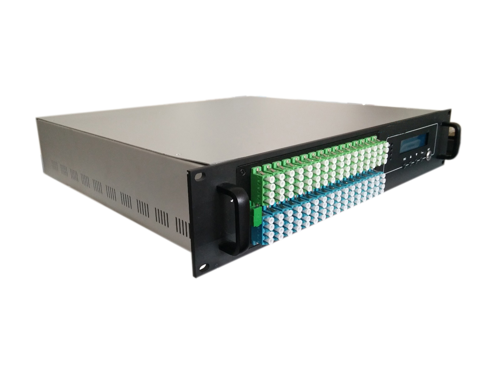
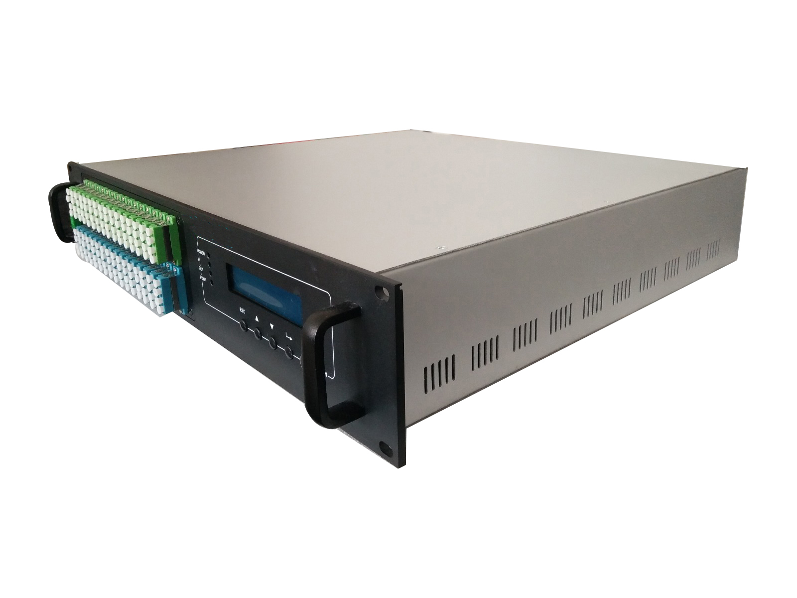
64 Ports EDFA
Built-in optical fwdm,it can transmit broadband network and CATV together.
Adopts Er Yb Codoped double-clad fiber technology;
Catv input ports: 1 optional
Olt input ports: 4-32 optional
Com Output ports: 4-32 optional;
Optical output power: total output up to 15W(41dBm);
Low noise figure: <6dB when input is 0dBm;
Perfect network management interface, in line with standard SNMP network management;
Intelligent temperature control system make the power consumption lower;

Item Unit Technique parameters Remark Operating bandwidth nm 1545 - 1565 Optical input power range dBm -3 - +10 Max rang:-10-+10 Optical Switching time ms ≤ 5 Maximum optical output power dBm 41 Output power stability dBm ±0.5 Noise figure dB ≤ 6.0 Optical input power 0dBm, λ=1550nm Return loss Input dB ≥ 45 Output dB ≥ 45 Optical Connector Type CATV IN:SC/APC, PON:SC/PC OR LC/PC COM:SC/APC OR LC/APC PON to COM port insertion loss ≤ 1.0 dBm C/N dB ≥ 50 Test condition according to GT/T 184-2002. C/CTB dB ≥ 63 C/CSO dB ≥ 63 Power supply voltage V A: AC100V – 260V (50 Hz~60Hz) B: DC48V(50 Hz~60Hz) C:DC12V(50 Hz~60Hz) Operating temperature range °C -10 – +42 Maximum operating relative humidity % Max 95% no condensation Maximum storage relative humidity % Max 95% no condensation Dimension mm 483(L)×440(W)×88(H)
Installation steps
1. Before installing the equipment, please read the carefully and install the equipment according to the . Note: For the man-made damage and other all consequence caused by error installation that not according to the , we will not be responsible and will not supply free warranty.
2. Take out the device from the box; fix it to the rack and reliably grounding. (The grounding resistance must be < 4Ω).
3. Use the digital multimeter to check the supply voltage, make sure the supply voltage comply with the requirements and the switch key is on the “OFF” position. Then connect the power supply.
4. Input the optical signal according to the display message. Turn the switch key to the “ON” position and observe the front panel LED status. After the pump working status indicator turn into green, the device is working normal. Then press the menu button on the front panel to check the working parameters.
5. Connect the optical power meter to the optical signal output end by the standard optical fiber test jumper, then measure the optical output power. Affirm the measured optical output power and the displayed power are the same and have reached the nominal value. (Affirm the optical power meter is on 1550nm wavelength test position; the optical fiber test jumper is the matched one and on the connector surface has no pollution.) Remove the standard optical fiber test jumper and optical power meter; connect the device to the network. So far, the device has been completely installed and debugged.


